|
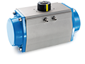
Standard actuators |

|
Standard quarter-turn actuator cams setting |
| |
|
| Download
|
|
|
Necessary equipment: • Valpes cam setting key (reference SJAJ593000) Steps summary: Step 1: Closed position setting (0 degree) - 2nd and 4th cams starting from the bottom • Actuator positioned at 0 degree • Closing detection cam (2nd) clockwise rotation until activation of the microswitch • Feedback detection cam (4th) clockwise rotation until activation of the microswitch +10° Step 2: Open position setting (90 degrees) - 1st and 3rd cams starting from the bottom • Actuator positioned at 90 degrees • Opening detection cam (1st) counter-clockwise rotation until activation of the microswitch • Feedback detection cam (3rd) counter-clockwise rotation until activation of the microswitch +10° |
|
|
Power supply card replacement on an ER actuator |
| |
|
| Download
|
|
|
Necessary equipment: • Cutting pliers • Flat pliers • Phillips screwdriver • Torx T10 screwdriver Steps summary: Step 1: Defective power supply card disassembly • Rotate manually the actuator into open position • Upper support unscrewing and disassembly • Switches card disassembly • A wire unplug from the power supply card and locate • C wire unplug from the power supply card • Disconnection of power supply terminals (1/2/3) • Unscrewing the 4 T10 torx of the power supply card • Power supply card disassembly Step 2: Mounting of the new power supply card • Place the new power supply card • Screwing the new power supply card with the 4 T10 torx • Connection of power supply terminals (3/1/2): 3=black / 1=red / 2=white • Place the switches card (be careful with the switches levers) • Replace the upper support and screw both parts • Reconnection of A wire (located) and C, on the new power supply card. |
Actuators with FAILSAFE security system |
|
|
ER FAILSAFE modification from normally closed to normally open |
| |
|
| Download
|
|
|
Necessary equipment: • Phillips screwdriver • Flat screwdriver • Pliers with thin nose Steps summary: Small ER models: • FAILSAFE card unscrewing and disassembly • 17 & 18 wires unplug • A & C wires inversion • FAILSAFE card replacement and screwing • 17 & 18 wires plug Big ER models • A & C wires inversion |
|
|
Mounting of EBS.24 FAILSAFE unit in a VS actuator |
| |
|
| Download
|
|
|
Necessary equipment: • Flat nose pliers • Phillips screwdriver • Insulation stripping pliers Kit EBS.24: • Battery pack + PCB • Two wires set • 4 screws Steps summary: • Mounting of the EBS.24 unit with the 4 screws • Strip the insulation of the 2 wires • Connect the wires to the FAILSAFE card - Watch polarities (red: E+ / black: E-) • Connect the set of two wires to the terminal 17/18 of the main card (red: 18 / black: 17) • Connect the FAILSAFE card (red: 18 / black: 17) |
Actuators with positioning system |
|
|
Mounting of a P5 unit in a VRA/VSA actuator |
| |
|
| Download
|
|
|
Necessary equipment: • Valpes setting key (reference SJAJ593000) • Circlip pliers • Cutting pliers • Flat screwdriver • Phillips screwdriver Kit P5: • Isolated spacer for upper support • P5 board • 2.2x16 screws • Z28 M0.5 gear • Z64 M0.5 gear • 13mm internal diameter circlips • 17/18 two wires kit Steps summary: Step 1: Switches board modification • Cable tie cutting • Disconnect A and B from the switches card • Disconnect A and C from power supply card • Unscrewing upper support • Disassembly of the upper support and the switches card • Unsold the A and C wires from the switches card • Sold a 19mm long on C (switches card) • Mounting of the modified switches card • Mounting of the upper support • Fastening of the switches card and the upper support • Connect motor wire to B (switches card): VRA25= black / VRA45= black / VRA75=red / VSA100= red / VSA150= black / VSA300= black Step 2: Mounting of the P5 unit • Shaft positioned at 0° (closed position) • Spacer mounting • P5 Positioning PCB mounting • Fastening of the P5 PCB with the 2 screws 2.2x16 • Z28 gear mounting • Z64 gear mounting • Circlip mounting • Shaft rotation clockwise up to mechanical end stop • Rotation clockwise of the Z64 gear up to potentiometer mechanical end stop • 5° anticlockwise rotation Step 3: Connections • Connect 17/18 (card) to 17/18 (power supply card) • Connect the second motor wire on A (P5 PCB) • Connect C (sold wire on switches card) to C (P5 PCB) For the P5 unit setting, see the video GP6 (ER+) and GP5 (VR/VS) positioning card setup in this section |
|
|
GP6 (ER+) and GP5 (VR/VS) positioning card setup |
| |
|
| Download
|
|
|
Steps summary: 1. Setpoint signal selection (1) 1.1. Analog setpoint signal (4 to 20mA) • Switch off the actuator • K1, K2 and K3 jumpers setting (configuration: 4-20mA setpoint signal and 4-20mA feedback signal) • Press MEM and CLOSE buttons and put the power on while kipping these buttons pressed, the red LED blinks 3 times • Release MEM and CLOSE buttons • Disconnect the card 1. Setpoint signal selection (2) 1.2. Voltage input signal (0 to 10V) • Switch off the actuator • K1, K2 and K3 jumpers setting (configuration: 0-10V setpoint signal and 0-10V feedback signal) • Press MEM button and put the power on while kipping this button pressed, the red LED blinks 3 times • Release MEM button • Disconnect the card 2. Learning mode (OPEN and CLOSED position saving) • Switch off the actuator • Press OPEN and CLOSE buttons and put the power on while kipping these buttons pressed, the both LEDs light up • Release OPEN and CLOSE buttons, the both LEDs go off. The learning mode is selected • Push CLOSE button to drive the valve to closed position, the red LED lights up • Store the closed position by pushing both MEM and CLOSE buttons at the same time, the red light blinks two times • Push OPEN button to drive the valve to opened position, the green LED lights up • Store the open position by pushing both MEM and OPEN buttons at the same time, the green light blinks two times • The both positions are recorded, disconnect the card 3. Selection of the valve direction (1) 3.1. Normal direction (clockwise closing): closed = 4mA or 0V and open = 20mA or 10V: • Switch off the actuator • Press OPEN button and put the power on while kipping this button pressed, the green LED lights up • Release OPEN button • Disconnect the card 3. Selection of the valve direction (2) 3.1. Reversed direction (clockwise opening): closed = 20mA or 10V and open = 4mA or 0V): • Switch off the actuator • Press CLOSE button and put the power on while kipping this button pressed, the red LED lights up • Release CLOSE button • Disconnect the card |
|
|
Dismantling of a P6 unit |
| |
|
| Download
|
|
|
Necessary equipment: • Phillips screwdriver • Cutting pliers • Circlip pliers Steps summary: • Unplug wires 17/18 from the power supply card • Unplug wires 17/18 from the P6 card • Cut the clamping ring • Unplug the C wire from the P6 card • Unplug the A wire from the P6 card • Circlip disassembly • Z64 gear disassembly • Remove the screws • P6 card disassembly • Cut the second clamping ring • Plug wire A (contact card) to A (power supply card) • Plug motor wire to the C (power supply card) |
3-position actuators |
|
|
3-position actuator cams setting |
| |
|
| Download
|
|
|
Necessary equipment: • Valpes cam setting key (reference SJAJ593000) Steps summary: Step 1: first position setup (0 degree), 2nd and 6th cams (starting from the bottom) • Actuator positioned at 0 degree • Closing detection cam (2nd) clockwise rotation until activation of the microswitch • Feedback detection cam (6th) clockwise rotation until activation of the microswitch +10° Step 2: second position setup (180 degrees), 1st and 5th cams (starting from the bottom) • Actuator positioned at 180 degrees • Opening detection cam (1st) counter-clockwise rotation until activation of the microswitch • Feedback detection cam (5th) counter-clockwise rotation until activation of the microswitch +10° Step 3: intermediate position setup (90 degrees), 3rd, 4th and 7th cams (starting from the bottom) • Actuator positioned at 87 degrees • First intermediate position detection cam (3rd) counter-clockwise rotation until activation of the microswitch • Actuator positioned at 93 degrees • Second intermediate position detection cam (4th) clockwise rotation until activation of the microswitch • Actuator positioned at 80 degrees • Intermediate position feedback cam (7th) clockwise rotation until deactivation of the microswitch |
Options |
|
|
Mounting of a EPT.C unit in a ER actuator |
| |
|
| Download
|
|
|
Necessary equipment: • Phillips screwdriver • Circlip pliers • Valpes setting key (reference SJAJ593000) Kit EPT.C: • EPT.C board • 2 screws • Z28 gear • Z64 gear • Circlip Steps summary: • Shaft positioned at 0° (closed position) • EPT.C board mounting • Screwing (2 screws) • Z28 gear mounting • Z64 gear mounting • Circlip mounting • Shaft rotation clockwise up to mechanical end stop • Rotation clockwise of the Z64 gear up to potentiometer mechanical end stop • 5° reverse rotation |
|
|
Dismantling of a EPT.C unit from an ER actuator |
| |
|
| Download
|
|
|
Necessary equipment: • Phillips screwdriver • Circlip pliers Steps summary: • Circlip disassembly • Z64 gear disassembly • Z28 gear disassembly • Unscrewing • EPT.C card disassembly |
|
|
EPT.C card setup |
| |
|
| Download
|
|
|
Steps summary: Step 1: Initialization • Disconnect the card • Press MEM, CLOSE and OPEN buttons and put the power on while kipping these buttons pressed, both LEDs light up • Release the buttons and wait for both LEDs go off • Disconnect the card Step 2: Feedback signal selection • Jumpers setting: ◊ for 4-20mA: 1=ON / 3=ON / 4=OFF ◊ for 0-20mA: 1=OFF / 3=ON / 4=OFF ◊ for 0-10V: 1=OFF / 3=OFF / 4=ON • For 4-20mA: ◊ Press MEM and CLOSE buttons and put the power on while kipping these buttons pressed, the red LED blinks 3 times ◊ Release the buttons and disconnect the card • For 0-20mA: ◊ Press MEM and OPEN buttons and put the power on while kipping these buttons pressed, the red LED blinks 3 times ◊ Release the buttons and disconnect the card • For 0-10V: ◊ Press MEM button and put the power on while kipping this button pressed, the red LED blinks 3 times ◊ Release the button and disconnect the card Step 3: Learning mode • Disconnect the card • Press OPEN and CLOSE buttons and put the power on while kipping these buttons pressed, both LEDs light up • Release the buttons, both LED go off, the learning mode is selected • Operate electrically the actuator to its closed position • Store the closed position by pressing both MEM and CLOSE buttons, the red LED blinks 2 times • Operate electrically the actuator to its open position • Store the open position by pressing both MEM and OPEN buttons, the green LED blinks 2 times • Both positions are recorded, disconnect the card. |
|
|
Mounting of a EPR.B unit in a ER actuator |
| |
|
| Download
|
|
|
Necessary equipment: • Phillips screwdriver • Hexagonal screwdriver or key (BTR) - size 2 • Circlip pliers • Valpes setting key (reference SJAJ593000) Kit EPR.B: • EPR.B board • 4 screws • Z14 gear • Z32 gear • Circlip Steps summary: • Shaft rotation clockwise up to mechanical end stop • EPR.B board mounting and screwing (4 screws) • Z14 gear mounting and screwing (2 screws) • Z32 gear mounting • Circlip mounting • Rotation clockwise of the Z32 gear up to potentiometer mechanical end stop • 5° reverse rotation |